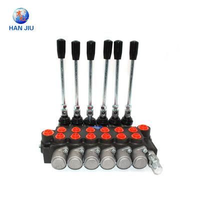
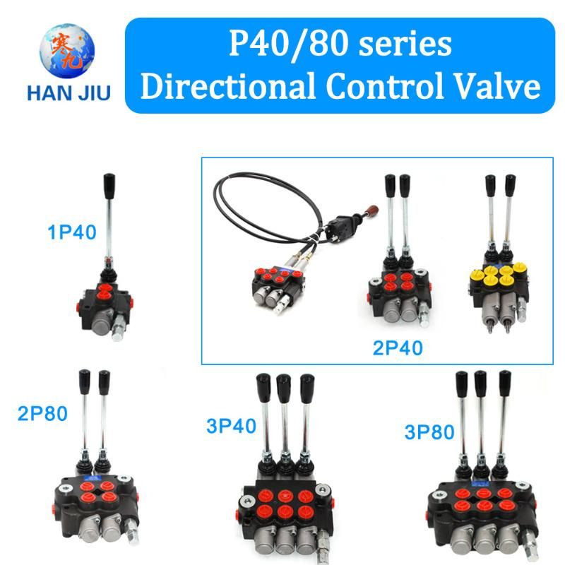
Hydraulic Directional Valve Diagram 6p40
Changzhou Kaiguan Packaging & Technology Co., Ltd. / 2022-06-27
- Function:Flow Control
- Installation:Threaded Cartridge
- Drive:Hydraulic
- Type:Directly Operated Type
- Spool:1, 2, 3, 4, 5, 6, ...
- Flow:40lt, 50lt, 60lt, 90lt, 100lt, 120lt, 140lt, ...
=== Base Info ===
- Model NO.:6p40
- Transport Package:Carton, Pallet
- Specification:20KGS
- Trademark:HANJIU
- Origin:China
- HS Code:8481802990
- Production Capacity:10000 Pieces
=== Description ===
Basic Info.
Model NO. 6p40 Transport Package Carton, Pallet Specification 20KGS Trademark HANJIU Origin China HS Code 8481802990 Production Capacity 10000 PiecesProduct Description
hydraulic directional valve diagram 6p40Description
Manually or mechanically controlled hydraulic Monoblock Control Valves is designed for distribution and control of work flow between generator (pump) and executive mechanisms (cylinder, hydro-motor, etc.). It is manufactured with 1 to 7 plungers, with parallel or serial action, with common or individual back valve for each plunger, with or without safety valve.
ConstructionThis valve is a mono-bloc distributor. Its body is made of cast iron EN-GJL300. Plungers are made of carburized steel with hard chrome plating.
MountingThe distributor is fixed with two bolts M8
New product
Hot product
- Gm Candi Interface
2022-06-23
- Scan Dash V2.0 for BMW
2022-06-23
- K+Can Commander 2.0
2022-06-23
- Mut-3 Professional Diagnostic Tool Mut3
2022-06-23
- CKM-100 Key Programmer for Benz/BMW
2022-06-23
- Fuel Injector Tester & Cleaner (MST-N6A)
2022-06-23
- Mst 9000+ Plus ECU Simulator
2022-06-23
- OBD Ii Code Reader Mst-300, OBD2 Code Scanner
2022-06-23
- Digital Battery Analyzer (SC-100)
2022-06-23
- VAS5052A PC VERSION with VAS5054A Wireless Bluetooth Communicate
2022-06-23

